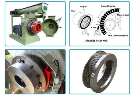
Die and roller interaction
The die and rollers interact to create a wedge of feed at the nip in the pellet mill. The three main forces in this process are:
- Roll force: The force from the roll acting on the This force acts on the material relative to the contact point with the die. It is a force that acts to compress and extrude the material.
- Radial force: The force from the die that resists the flow of material through the die
- Tangential force: The force along the face of the die that keeps the material from sliding along the face of the die in front of the This force is related to the pressure exerted by the roll and the frictional characteristics of the feed.
These forces are determined by several factors.
Feed rate
The rate that feedstock is fed to the die and rollers is the feed rate. More feedstock in the pelleting chamber creates a thicker layer of raw material. This results in a greater portion of the roll force pushing the feedstock forward instead of down through the die holes. Blockage is more likely to occur if raw material is fed too quickly. The mat of feed can build up to where it can’t be grabbed by the textured surface of the rollers. The pelleting chamber then fills with feed until the flow is stopped. Such variations in the feed rate and the roll force also cause fluctuations in the motor load.
Feed distribution
Equal feed distribution to each roller and across the face of the die must be maintained for a consistent production rate. The density of the feedstock being pelleted and the feed rate affects this distribution.
Roller setting
The roller must be adjusted downward to a proper relationship with the die or the roll will not turn. The roller is always turning about its contact point with the die. Any time this is disturbed, the roller wants to act as a plough forcing the material along the face of the die rather than down through the die holes. Use a “touch and skip” method to set the rollers. Rollers will damage the die if the two are in direct contact. The gap is the distance between the die and rollers. Be mindful of the following when setting the gap:
Gap of 1 millimeter: Generally a distance of 1 millimeter is regarded as optimum for most materials to give the correct balance between pellet quality, energy input and equipment wear. Increasing the gap from 0 to 1 millimeter increases the energy demand by a factor of 1.2, however fines are reduced by up to 30% and wear of the die and rollers is reduced.
Gap greater than 1 millimeter: The larger the gap between the rollers and die, the greater the energy input required. If the rollers are set above 1 millimeter, there may not be enough pressure generated between the die and rollers. Without pressure there is no heat, no binder is released and a carpet cannot form, thus a pellet cannot form.
Less than 1 millimeter gap: As the rollers and die touch there is no room to form a carpet of material, thereby forcing the material directly through the die holes which reduces pellet quality. More importantly there is metal to metal contact, significantly reducing the life of the roller and die.
When setting roller gaps the characteristics of the material must also be considered. For example, material density and binding properties will influence the optimal gap size. A 1 millimeter gap is recommended for most materials. However, experimenting with different gap sizes will prove beneficial.
Frictional characteristics of the feedstock
The frictional characteristics of raw material influence the action at the nip between the roller and die. If excessive moisture is added through conditioning, the feedstock tends to become slippery beneath the roller assembly. This alters the driving force that turns the roller. The roller will begin to plough the material ahead of itself. The raw material has then lost its ability to turn the roller. Moisture fluctuation in the conditioned feedstock varies the frictional characteristics of the pellet mill.
Die hole counts
This is the total number of holes for a given die. For a die to produce at maximum capacity, the distance between the holes should be minimized—this allows for the maximum number of holes. However, if the holes are too close together the die may break. The three hole count types are:
- Close hole count: This type of die is suitable for less demanding feedstock where maximum die strength is not a factor such as broiler
- Standard hole count: This type of die is used in general purpose pelleting and is tolerant of a broad range
- Heavy duty hole count: The die is specially designed for a specific pelleting application where extreme pressures and stresses may be Materials with a high mineral content may require such a die.
Die hole configurations
Tapered entry die: A type of entry more often in large hole dies (greater than 10 mm). The taper consists of reamer angle and reamer depth. Reamer angles vary while the taper depth is usually from 20 to 50 mm. Generally, tapers are not severe angles and are used to moderately increase compression. Well dies are used for greater compression requirements.
Well die: A type of hole entry in large hole dies (greater than 12 mm in diameter). The hole entry is substantially larger than the actual hole size. Hole depth is predetermined based on hole diameter. Well dies offer greater versatility to handle variations in feedstock.
Well die-tapered bottom: The well has a slight taper at the bottom leading to the true hole size. The taper is a transition between the well and hole.
Well die-flat bottom: The well in this die has a flat bottom and there is no taper transition. Maximum compression is obtained with this die.
Straight relief: The relief in the die is uniform across the die to obtain the desired effective thickness.
Variable relief: The outside two or three rows are lowered about 1 cm, thus reducing the effective thickness of these holes. The purpose is to improve material flow through these outer holes.
Staggered variable relief: A predetermined number of holes are relieved in “step fashion” across the die face. Usually one third of the die holes are the true effective thickness, one third at about 1 cm below this level, and the final third a centimeter below this. The center third of the die is at the full effective thickness; one sixth of the holes on each side are relieved 8 mm and the remaining one sixth on each side are relieved 12 mm.
Straight hole die (no relief): This is a die with a common hole size the full thickness of the die.
Die material composition
Alloy steel: This type of steel has one or more elements added to provide improved strength and toughness over plain carbon steel. This metal is satisfactory for pelleting most materials. If corrosive problems occur, stainless steel dies may need to be used.
Standard stainless steel: Stainless steel is an iron carbon alloy in which chromium has been added in order to provide superior corrosion resistance, as well as resistance to pitting, scoring and corrosion. With stainless steel, less enlargement of the die hole occurs compared to alloy dies.
Chrome-plus stainless steel: A higher quality stainless steel with higher percentages of chromium and nickel to improve the corrosion resistance over stainless steel. This metal may be needed for very abrasive or corrosive feedstock.


